Home » Without Label » 3 Way Switch Wiring / electrical - Wiring existing 3 Way Switch in basement ... : Pick the diagram that is most like the scenario you are in and see if you can wire your switch!
3 Way Switch Wiring / electrical - Wiring existing 3 Way Switch in basement ... : Pick the diagram that is most like the scenario you are in and see if you can wire your switch!
3 Way Switch Wiring / electrical - Wiring existing 3 Way Switch in basement ... : Pick the diagram that is most like the scenario you are in and see if you can wire your switch!. Video includes the bonus addition of addi. This might seem intimidating, but it does not have to be. Three way switch wiring with light middle the source in this circuit is at the first switch and the light fixture is located between sw1 and sw2. In the 3 way configuration depicted on this page, the white wire going from the fixture to switch 1 and the white wire going from switch 1 to switch 2 have been used to carry a switched ungrounded conductor (hot) part of the circuit and therefore as stated should have a piece of black electrical tape wrapped around that wire in the box. The hot source wire is connected to the common terminal on sw1.
(learn more about how our awesome backlit switches work here) even that one is still pretty straightforward though, here are some diagrams that show the single jumper required on the back of the switch. Take a closer look at a 3 way switch wiring diagram. The hot source wire is connected to the common terminal on sw1. Three way switching schematic wiring diagram. Notice that the wire connected to the com terminals is looped straight through.
3 Way Switch Wiring Diagram | 3 way switch wiring ... from i.pinimg.com Three way switching schematic wiring diagram. There are several types of light switches that you will encounter when upgrading a switch to a smart switch in your home. Connect 3 wire cable in the first switch box. (learn more about how our awesome backlit switches work here) even that one is still pretty straightforward though, here are some diagrams that show the single jumper required on the back of the switch. This might seem intimidating, but it does not have to be. In this configuration, the power enters the first switch, and the light fixture is placed after the second switch. Power from the panel with 14/2 would come into the light box first or the octagon. In this case, electricity flows through the ceiling box from the first switch to the second switch.
The 3 wire cable enters through the top of the first switch box.
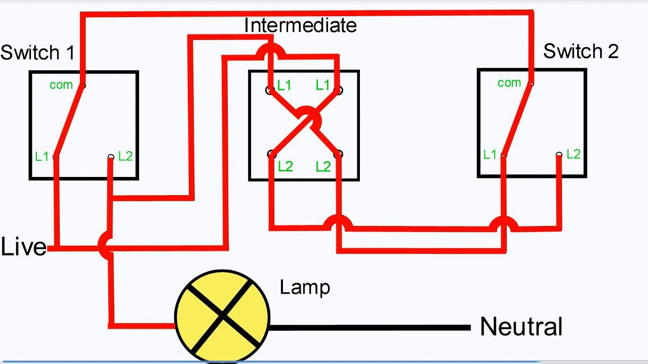
All three switches are connected together by a three core and earth control cable. The white wire from the power panel would help directly on to the light fixture. Notice that the wire connected to the com terminals is looped straight through. (learn more about how our awesome backlit switches work here) even that one is still pretty straightforward though, here are some diagrams that show the single jumper required on the back of the switch. With these diagrams below it will take the guess work out of wiring. The circuit consists of a two way switch at each end (top and bottom switches in fig 2) and an intermediate switch in the middle. Pick the diagram that is most like the scenario you are in and see if you can wire your switch! The white wire becomes the energized switch leg, as indicated by using black or red electrical tape. Power from the panel with 14/2 would come into the light box first or the octagon. Video includes the bonus addition of addi. Of the three bilge pump switches the only one that's not extremely simple is the backlit auto/manual bilge pump switch. 3 way switch wiring diagram. Assortment of fender telecaster 3 way switch wiring diagram.
This might seem intimidating, but it does not have to be. Assortment of fender telecaster 3 way switch wiring diagram. C) the wires from the power source go from switch to switch, and then go to the light. Notice that the wire connected to the com terminals is looped straight through. The ground wire is pigtailed with a wire connector at the switch boxes and the ceiling box.
3-way Switch Wiring - Electrical 101 from www.electrical101.com Take a closer look at a 3 way switch wiring diagram. Of the three bilge pump switches the only one that's not extremely simple is the backlit auto/manual bilge pump switch. This is the most common light switch found in a home. With these diagrams below it will take the guess work out of wiring. There are several types of light switches that you will encounter when upgrading a switch to a smart switch in your home. Wire the 3 way with power in the switch. This 3 way switch wiring diagram shows how to wire the switches and the light when the power is coming to the light switch. Connect 3 wire cable in the first switch box.
With these diagrams below it will take the guess work out of wiring.
There are several types of light switches that you will encounter when upgrading a switch to a smart switch in your home. Red wire (traveler or switch wire). Video includes the bonus addition of addi. Of the three bilge pump switches the only one that's not extremely simple is the backlit auto/manual bilge pump switch. The circuit consists of a two way switch at each end (top and bottom switches in fig 2) and an intermediate switch in the middle. The ground wire is pigtailed with a wire connector at the switch boxes and the ceiling box. All three switches are connected together by a three core and earth control cable. It shows the parts of the circuit as simplified forms, as well as the power and signal connections in between the tools. Pick the diagram that is most like the scenario you are in and see if you can wire your switch! Assortment of fender telecaster 3 way switch wiring diagram. In the 3 way configuration depicted on this page, the white wire going from the fixture to switch 1 and the white wire going from switch 1 to switch 2 have been used to carry a switched ungrounded conductor (hot) part of the circuit and therefore as stated should have a piece of black electrical tape wrapped around that wire in the box. This is the most common light switch found in a home. The white wire of the cable going to the switch is attached to the black line in the fixture box using a wire nut.
The white wire from the power panel would help directly on to the light fixture. Red wire (traveler or switch wire). This 3 way switch wiring diagram shows how to wire the switches and the light when the power is coming to the light switch. With these diagrams below it will take the guess work out of wiring. It shows the parts of the circuit as simplified forms, as well as the power and signal connections in between the tools.
Three-Way Switch Diagram For Dummies | Printable Diagram ... from 2020cadillac.com These wires connect to the brass screws on the switch. It shows the parts of the circuit as simplified forms, as well as the power and signal connections in between the tools. (learn more about how our awesome backlit switches work here) even that one is still pretty straightforward though, here are some diagrams that show the single jumper required on the back of the switch. To connect the switches, simply score the wire with your wire stripper and push the insulation to expose about 3/4 in. In this configuration, the power enters the first switch, and the light fixture is placed after the second switch. Assortment of fender telecaster 3 way switch wiring diagram. This 3 way switch wiring diagram shows how to wire the switches and the light when the power is coming to the light switch. In the 3 way configuration depicted on this page, the white wire going from the fixture to switch 1 and the white wire going from switch 1 to switch 2 have been used to carry a switched ungrounded conductor (hot) part of the circuit and therefore as stated should have a piece of black electrical tape wrapped around that wire in the box.
With these diagrams below it will take the guess work out of wiring.
Take a closer look at a 3 way switch wiring diagram. Video includes the bonus addition of addi. Pick the diagram that is most like the scenario you are in and see if you can wire your switch! Wire the 3 way with power in the switch. In the 3 way configuration depicted on this page, the white wire going from the fixture to switch 1 and the white wire going from switch 1 to switch 2 have been used to carry a switched ungrounded conductor (hot) part of the circuit and therefore as stated should have a piece of black electrical tape wrapped around that wire in the box. This might seem intimidating, but it does not have to be. Notice that the wire connected to the com terminals is looped straight through. The white wire becomes the energized switch leg, as indicated by using black or red electrical tape. The circuit consists of a two way switch at each end (top and bottom switches in fig 2) and an intermediate switch in the middle. Three way switch wiring with light middle the source in this circuit is at the first switch and the light fixture is located between sw1 and sw2. 2 wire cable runs from the light to the first switch, and then 3 wire is run between all the switches. These wires connect to the brass screws on the switch. The white wire of the cable going to the switch is attached to the black line in the fixture box using a wire nut.